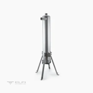
Description
HOW IT WORKS
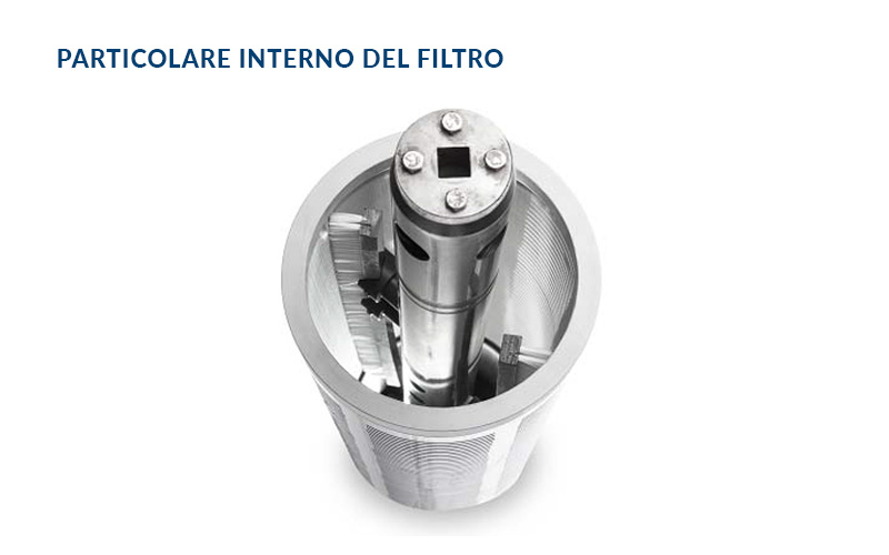
Water enters the filter through the inlet (IN), it goes through the filtering cylinder (1) from inside out, which retains the suspended filters to be filtered; it retains all suspended solids with size larger or equal to the filtration degree installed. Filtered water leaves through the master valve (OUT).
REGENERATION
The continuous settling of suspended solids obstructs the passage of water which results in a pressure difference (∆P). At a preset value of ∆P (range 0.3 ÷ 1 Bar) an automatic cycle will start to clean the filter cylinder (1). This operation starts with a signal that closes the outlet valve, (2) which clears the ∆P, and opens the discharge valve (3). At the same time the electric motor (4) rotates the brushes (5) in the filtering cylinder to clear away the contaminant that is ejected through the discharge valve (3). The cleaning cycle lasts approximately 20 seconds.
CONTROL
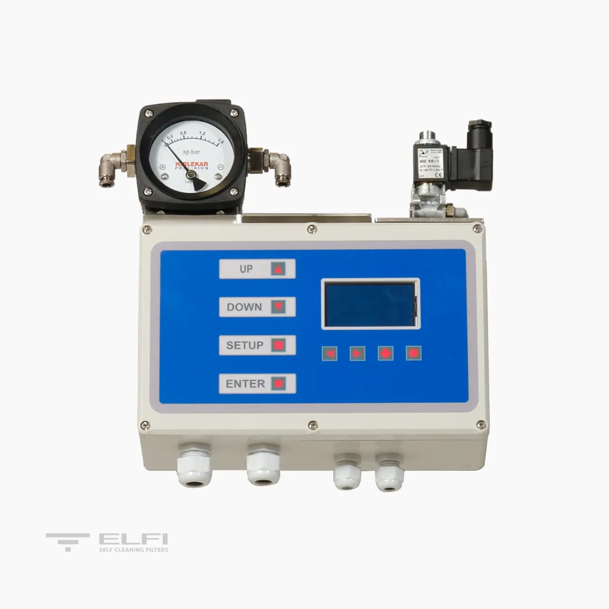
A switchboard controls the washing phases. The signal that starts the cleaning cycle is given by a differential pressure switch or by time. The switchboard gives an “alarm” signal in case of problems in the washing system. These signals can be sent to a pre-existing control centre. The washing phase can also be controlled manually. The solenoid controlling the valve is pneumatic.
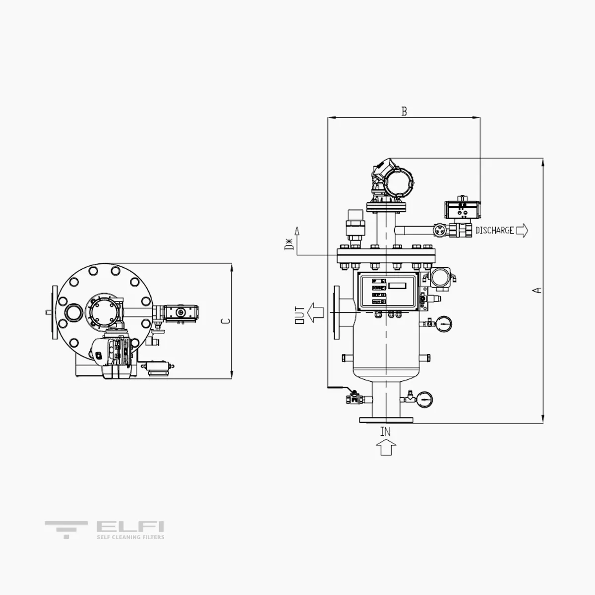
TECHNICAL DATA AND DIMENSIONS | SP L

| MODEL | SP L 10 | SP L 15 | SP L 30 | SP L 45 | SP L 60 | SP L 75 | SP L 90 | SP L 130 |
|---|---|---|---|---|---|---|---|---|
| Filtering area (cm²) | 1000 | 1500 | 3000 | 4500 | 6000 | 7500 | 9000 | 13000 |
| Connections- In/Out | 2" | 3" | DN100 | DN150 | DN200 | DN250 | DN300 | DN350 |
| Discharge connection | 1" F | 1" F | 1 1/2" F | 1 1/2" F | 1 1/2" F | 1 1/2" F | 1 1/2" F | 2" F |
| Draining connections | 1/2" F | 1/2" F | 1/2" F | 1/2" F | 1/2" F | 1 1/2" F | 1" F | 1" F |
| Extra flow rate required during washing at 1 Bar with mesh from 800 to 80 micron – m³/h | 2 | 3 | 4 | 7 | 9 | 9 | 9 | 15 |
| Wash duration - Sec | 20 | 20 | 20 | 20 | 20 | 20 | 20 | 20 |
| Min-max pressure – Bar | 0,5-10 | 0,5-10 | 0,5-10 | 0,5-10 | 0,5-10 | 0,5-10 | 0,5-10 | 0,5-10 |
| Max Temperature - °C | 50 | 50 | 50 | 50 | 50 | 50 | 50 | 50 |
| Power supply – Volt | 400 50/60 Hz | 400 50/60 Hz | 400 50/60 Hz | 400 50/60 Hz | 400 50/60 Hz | 400 50/60 Hz | 400 50/60 Hz | 400 50/60 Hz |
| Power required – Watt | 90 | 180 | 180 | 180 | 370 | 370 | 370 | 550 |
| Solenoid valve – Volt /Watt | 24 AC /6 | 24 AC /6 | 24 AC /6 | 24 AC /6 | 24 AC /6 | 24 AC /6 | 24 AC /6 | 24 AC /6 |
| Pneumatic supply - Bar | 2 - 8 | 2 - 8 | 2 - 8 | 2 - 8 | 2 - 8 | 2 - 8 | 2 - 8 | 2 - 8 |
| Construction certificates | CE | CE | CE | CE | CE | CE | CE | CE |
| Maximum size of inlet particles – mm | 10 | 10 | 10 | 10 | 10 | 10 | 10 | 10 |
| Max total suspendedsolids at inlet 125 micron – mg/l | 30 | 30 | 30 | 30 | 30 | 30 | 30 | 30 |
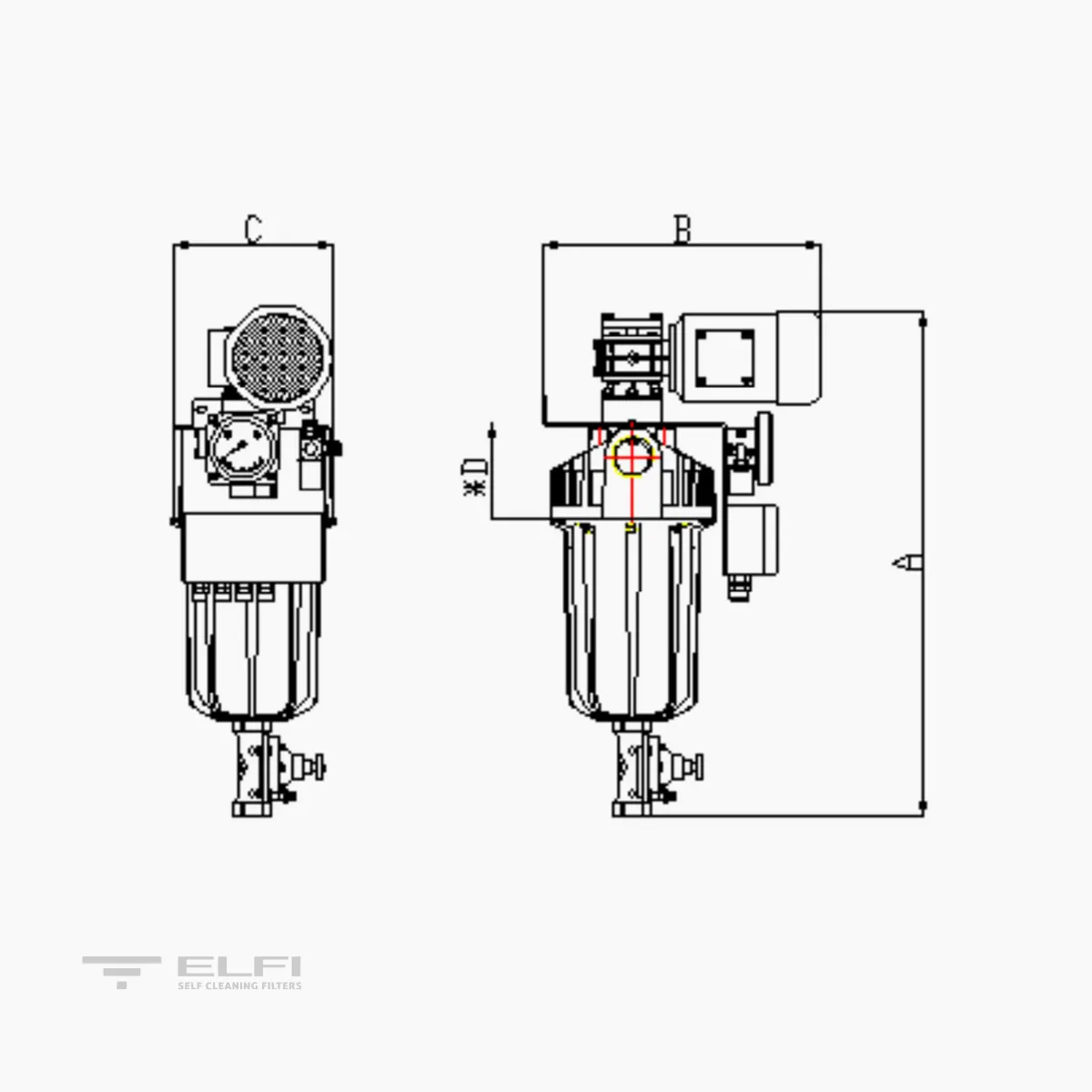
| A (mm) | 757 | 903 | 1071 | 1309 | 1755 | 2027 | 2581 | 3181 |
| B (mm) | 485 | 505 | 645 | 745 | 800 | 905 | 968 | 1114 |
| C (mm) | 327 | 423 | 423 | 516 | 714 | 852 | 852 | 852 |
| D (mm) Cartridge extraction | 450 | 600 | 640 | 885 | 1130 | 1160 | 1160 | 1690 |
| WEIGHT when empty Kg | 34 | 51 | 62 | 72 | 85 | 127 | 223 | 305 |
| WEIGHT in operation Kg | 42 | 51 | 81 | 116 | 143 | 214 | 356 | 618 |
TECHNICAL DATA AND DIMENSIONS | SP O
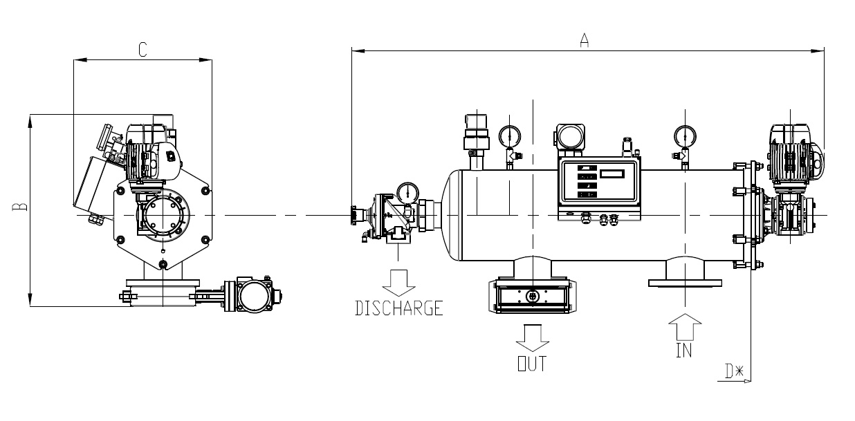
| MODEL | SP O 10 | SP O 15 | SP O 30 | SP O 45 | SP O 60 | SP O 75 | SP O 90 | SP O 130 |
|---|---|---|---|---|---|---|---|---|
| Filtering area (cm²) | 1000 | 1500 | 3000 | 4500 | 6000 | 7500 | 9000 | 13000 |
| Connections- In/Out | 2" | 3" | DN100 | DN150 | DN200 | DN250 | DN300 | DN350 |
| Discharge connection | 1"1/2F | 1"1/2F | 2"F | 2"F | 2"F | 2"F | 2"F | 2"F |
| Washing flow rate - m³/h | 5 | 10 | 15 | 20 | 24 | 24 | 35 | 45 |
| Wash duration - Sec. | 15 | 15 | 15 | 15 | 15 | 15 | 15 | 15 |
| Min-max pressure - Bar | 0,5-10 | 0,5-10 | 0,5-10 | 0,5-10 | 0,5-10 | 0,5-10 | 0,5-10 | 0,5-10 |
| Max Temperature - °C | 50 | 50 | 50 | 50 | 50 | 50 | 50 | 50 |
| Power supply - Volt | 400 50/60 Hz | 400 50/60 Hz | 400 50/60 Hz | 400 50/60 Hz | 400 50/60 Hz | 400 50/60 Hz | 400 50/60 Hz | 400 50/60 Hz |
| Power required - Watt | 90 | 180 | 180 | 180 | 370 | 370 | 370 | 550 |
| Solenoid valve - Volt / Watt | 24 AC / 6 | 24 AC / 6 | 24 AC / 6 | 24 AC / 6 | 24 AC / 6 | 24 AC / 6 | 24 AC / 6 | 24 AC / 6 |
| Pneumatic supply - Bar | 2 - 8 | 2 - 8 | 2 - 8 | 2 - 8 | 2 - 8 | 2 - 8 | 2 - 8 | 2 - 8 |
| Construction certificates | CE | CE | CE | CE | CE | CE | CE | CE |
| Maximum size of inlet particles – mm | 30 | 30 | 30 | 30 | 30 | 30 | 30 | 30 |
| Max total suspended solids at inlet – 125 micron mg/l | 30 | 30 | 30 | 30 | 30 | 30 | 30 | 30 |
| A (mm) | 940 | 1185 | 1430 | 1675 | 1920 | 2055 | 2200 | 2700 |
| B (mm) | 470 | 585 | 590 | 595 | 625 | 685 | 885 | 1195 |
| C (mm) | 330 | 420 | 420 | 485 | 625 | 795 | 1040 | 1195 |
| D (mm) * Cartridge extractiona | 250 | 400 | 585 | 640 | 810 | 850 | 1040 | 1230 |
| WEIGHT when empty Kg | 25 | 29 | 46 | 52 | 82 | 125 | 200 | 288 |
| WEIGHT in operation Kg | 33 | 42 | 72 | 91 | 116 | 222 | 370 | 628 |
FILTERING MESH FLOW RATE TABLE FOR SP FILTERS (m3/h)
| MODEL | 800 µm PES AISI316 | 500 µm PES AISI316 | 300 µm PES AISI316 | 200 µm PES AISI316 | 125 µm PES AISI316 | 80 µm PES AISI316 |
|---|---|---|---|---|---|---|
| SP 10 | 30 | 30 | 30 | 30 | 30 | 30 |
| SP 15 | 80 | 80 | 80 | 80 | 80 | 80 |
| SP 30 | 147 | 147 | 147 | 147 | 147 | 111 |
| SP 45 | 216 | 216 | 216 | 216 | 216 | 166 |
| SP 60 | 315 | 315 | 315 | 315 | 315 | 222 |
| SP 75 | 573 | 573 | 573 | 573 | 395 | 277 |
| SP 90 | 720 | 720 | 720 | 720 | 473 | 333 |
| SP 130 | 1038 | 1038 | 1038 | 1038 | 682 | 373 |
The flow rates indicated refer to a load loss of 0.2 Bar with clean, filtered water.
PARTS DESCRIPTION
| PART | DESCRIPTION |
|---|---|
| Body | AISI316 – SAF2205 – SAF2507 |
| Cover | AISI316 – SAF2205 – SAF2507 |
| Connection threading | BSP |
| Connection threading | EN 1092-1 PN10 |
| Mesh support strainer | PVC – AISI316 |
| Filtering mesh | Polyester – AISI316: 500, 300, 200, 125, 80, 50, 25 µm |
| Brushes | PVDF |
| Brush support | PVC – AISI316 |
| Internal seals | NBR – EPDM |
| Reduction unit | Aluminium and carbon steel |
| Electric motor | Hot-painted aluminium |
| Solenoid valve | Five-way aluminium |
| Switchboard | ABS IP65 with front display |
| Differential pressure switch | Aluminium with parts in contact with liquid made of AISI 316 |
| Discharge valve | PP diaphragm with flow rate regulation |
| Outlet valves | Butterfly with AISI316 disc and double-acting pneumatic actuator |
| Pressure gauges | Stainless steel with 2″1/2 dial, radial connection and 0-10 Bar indication |
| Accessories (Plugs and adapters) | PP – PVC – AISI316 |
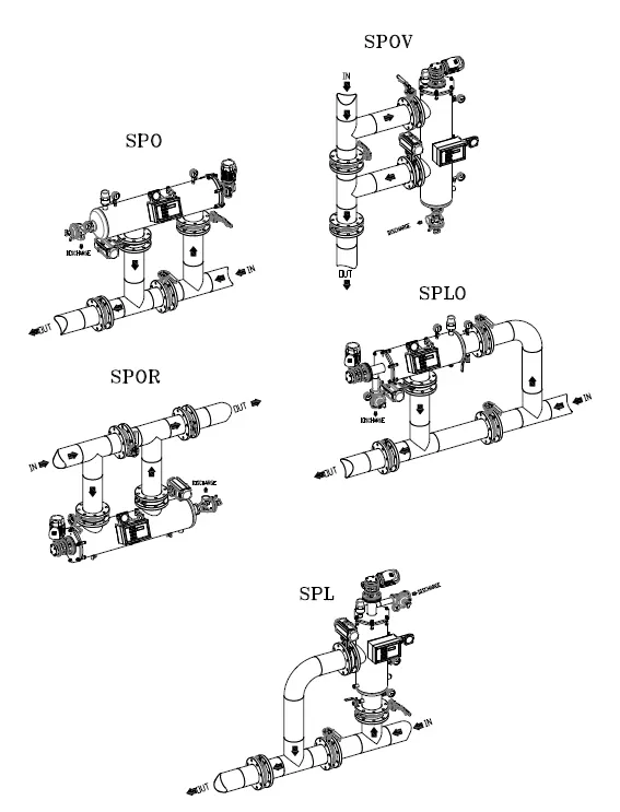
SUGGESTED INTALLATION
