


Description


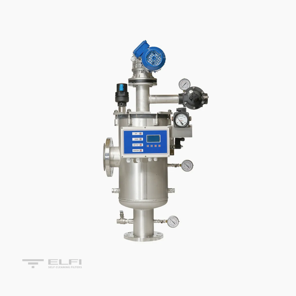
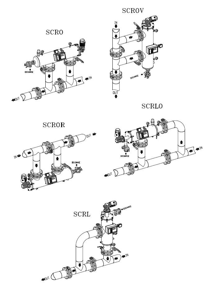
TECHNICAL DATA AND DIMENSIONS | SCR L DW
| MODEL | SCR L 10 | SCR L 15 | SCR L 30 | SCR L 45 | SCR L 60 | SCR L 75 | SCR L 90 | SCR L 130 |
|---|---|---|---|---|---|---|---|---|
| Filtering Area (cm²) | 1000 | 1500 | 3000 | 4500 | 6000 | 7500 | 9000 | 13000 |
| Connections- In/Out | 2" | 3" | DN100 | DN150 | DN200 | DN250 | DN300 | DN350 |
| Exhaust connections | 1" F | 1" F | 1"1/2 F | 1"1/2 F | 1"1/2 F | 1"1/2 F | 1" F | 2" F |
| Draining connections | 1/2" F | 1/2" F | 1/2" F | 1/2" F | 1/2" F | 1" F | 1" F | 1" F |
| 1 Bar washing flow rate with mesh from 500 to 25 micron – m³/h | 2 | 3 | 4 | 7 | 9 | 9 | 15 | 15 |
| Wash duration - Sec | 15 | 15 | 15 | 15 | 15 | 15 | 15 | 15 |
| Min-max pressure – Bar | 0,5-10 | 0,5-10 | 0,5-10 | 0,5-10 | 0,5-10 | 0,5-10 | 0,5-10 | 0,5-10 |
| Max Temperature - °C | 40 | 40 | 40 | 40 | 40 | 40 | 40 | 40 |
| Power supply – Volt | 400 50/60 Hz | 400 50/60 Hz | 400 50/60 Hz | 400 50/60 Hz | 400 50/60 Hz | 400 50/60 Hz | 400 50/60 Hz | 400 50/60 Hz |
| Power required – Watt | 90 | 90 | 180 | 180 | 180 | 370 | 370 | 550 |
| Solenoid valve – Volt / Watt | 24 AC / 6 | 24 AC / 6 | 24 AC / 6 | 24 AC / 6 | 24 AC / 6 | 24 AC / 6 | 24 AC / 6 | 24 AC / 6 |
| Pneumatic supply - Bar | 2-8 | 2-8 | 2-8 | 2-8 | 2-8 | 2-8 | 2-8 | 2-8 |
| Construction certificates | CE | CE | CE | CE | CE | CE | CE | CE |
| *Maximum size of inlet particles – mm | 3 | 3 | 3 | 3 | 3 | 3 | 3 | 3 |
| Max total suspended solids at inlet 125 micron – mg/l | 100 | 100 | 100 | 100 | 100 | 100 | 100 | 100 |
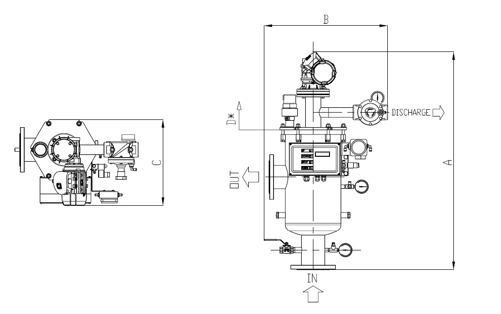
| A (mm) | 757 | 903 | 1071 | 1309 | 1755 | 2027 | 2581 | 3181 |
| B (mm) | 470 | 485 | 607 | 635 | 706 | 791 | 969 | 969 |
| C (mm) | 327 | 327 | 423 | 423 | 516 | 714 | 852 | 852 |
| D (mm) Cartridge extraction | 485 | 485 | 685 | 685 | 853 | 1130 | 1160 | 1160 |
| WEIGHT when empty Kg | 28 | 34 | 51 | 62 | 115 | 208 | 285 | 450 |
| WEIGHT in operation Kg | 36 | 42 | 70 | 86 | 133 | 202 | 346 | 598 |
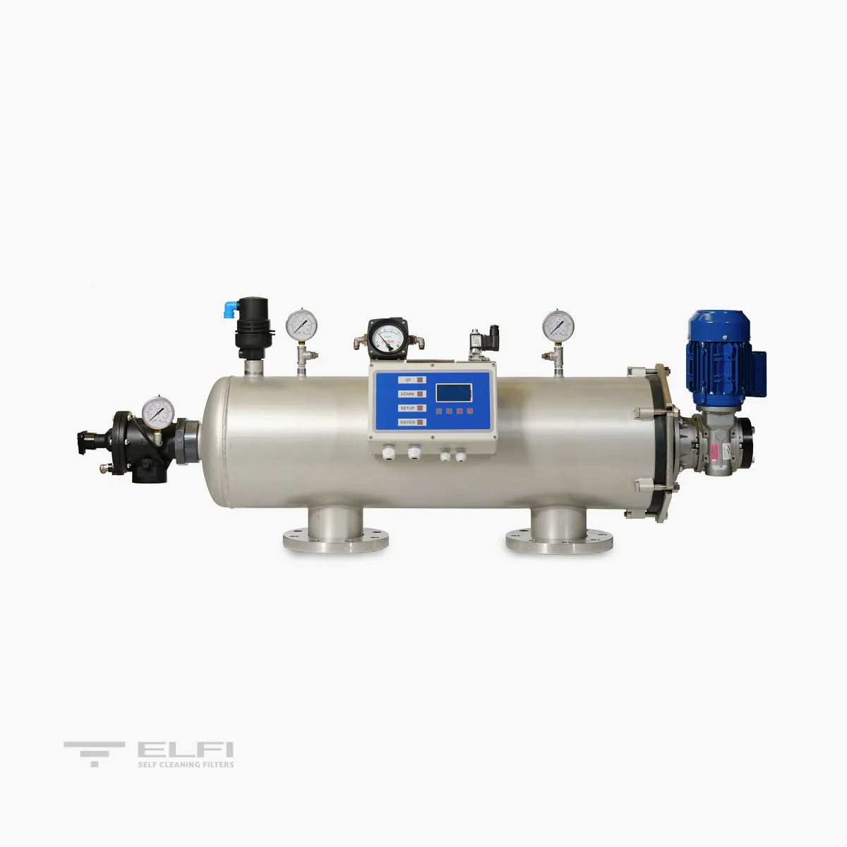
TECHNICAL DATA AND DIMENSIONS | SCR O DW

| MODELLO | SCRO 10 | SCRO 15 | SCRO 30 | SCRO 45 | SCRO 60 | SCRO 75 | SCRO 90 | SCRO 130 |
|---|---|---|---|---|---|---|---|---|
| Filtering area (cm²) | 1000 | 1500 | 3000 | 4500 | 6000 | 7500 | 9000 | 13000 |
| Connections- In/Out | 2" | 3" | DN100 | DN150 | DN200 | DN250 | DN300 | DN350 |
| Exhaust connections | 1"1/2 F | 1"1/2 F | 2" F | 2" F | 2" F | 2" F | 2" F | 2" F |
| Draining connections | 1/4" F | 1/4" F | 1/4" F | 1/4" F | 1/4" F | 1" F | 1" F | 1" F |
| 1 Bar washing flow rate with mesh from 500 to 25 micron – m³/h | 2 | 3 | 4 | 9 | 11 | 11 | 15 | 15 |
| Wash duration – Sec. | 15 | 15 | 15 | 15 | 15 | 15 | 15 | 15 |
| Min-max pressure – Bar | 0,5-10 | 0,5-10 | 0,5-10 | 0,5-10 | 0,5-10 | 0,5-10 | 0,5-10 | 0,5-10 |
| Max Temperature - °C | 40 | 40 | 40 | 40 | 40 | 40 | 40 | 40 |
| Power supply – Volt | 400 50/60 Hz | 400 50/60 Hz | 400 50/60 Hz | 400 50/60 Hz | 400 50/60 Hz | 400 50/60 Hz | 400 50/60 Hz | 400 50/60 Hz |
| Power required – Watt | 90 | 90 | 180 | 180 | 180 | 370 | 370 | 550 |
| Solenoid valve – Volt / Watt | 24 AC / 6 | 24 AC / 6 | 24 AC / 6 | 24 AC / 6 | 24 AC / 6 | 24 AC / 6 | 24 AC / 6 | 24 AC / 6 |
| Pneumatic supply – Bar | 2-8 | 2-8 | 2-8 | 2-8 | 2-8 | 2-8 | 2-8 | 2-8 |
| Construction certificates | CE | CE | CE | CE | CE | CE | CE | CE |
| Maximum size of inlet particles* – mm | 3 | 3 | 3 | 3 | 3 | 3 | 3 | 3 |
| Max total suspended solids at inlet 125 micron – mg/l | 100 | 100 | 100 | 100 | 100 | 100 | 100 | 100 |
| A (mm) | 900 | 1045 | 1430 | 1675 | 1920 | 2100 | 2205 | 2576 |
| B (mm) | 415 | 415 | 540 | 540 | 540 | 630 | 940 | 1114 |
| C (mm) | 330 | 410 | 410 | 430 | 460 | 634 | 678 | 700 |
| D (mm) Cartridge extraction | 450 | 570 | 640 | 885 | 1130 | 1130 | 1160 | 1690 |
| WEIGHT when empty Kg | 37 | 55 | 67 | 81 | 125 | 220 | 335 | 450 |
| WEIGHT in operation Kg | 38 | 91 | 105 | 114 | 152 | 222 | 370 | 633 |


