


Description


TECHNICAL DATA AND DIMENSIONS | SP L

| MODEL | SP L 10 | SP L 15 | SP L 30 | SP L 45 | SP L 60 | SP L 75 | SP L 90 | SP L 130 |
|---|---|---|---|---|---|---|---|---|
| Filtering area (cm²) | 1000 | 1500 | 3000 | 4500 | 6000 | 7500 | 9000 | 13000 |
| Connections- In/Out | 2" | 3" | DN100 | DN150 | DN200 | DN250 | DN300 | DN350 |
| Discharge connection | 1" F | 1" F | 1 1/2" F | 1 1/2" F | 1 1/2" F | 1 1/2" F | 1 1/2" F | 2" F |
| Draining connections | 1/2" F | 1/2" F | 1/2" F | 1/2" F | 1/2" F | 1 1/2" F | 1" F | 1" F |
| Extra flow rate required during washing at 1 Bar with mesh from 800 to 80 micron – m³/h | 2 | 3 | 4 | 7 | 9 | 9 | 9 | 15 |
| Wash duration - Sec | 20 | 20 | 20 | 20 | 20 | 20 | 20 | 20 |
| Min-max pressure – Bar | 0,5-10 | 0,5-10 | 0,5-10 | 0,5-10 | 0,5-10 | 0,5-10 | 0,5-10 | 0,5-10 |
| Max Temperature - °C | 50 | 50 | 50 | 50 | 50 | 50 | 50 | 50 |
| Power supply – Volt | 400 50/60 Hz | 400 50/60 Hz | 400 50/60 Hz | 400 50/60 Hz | 400 50/60 Hz | 400 50/60 Hz | 400 50/60 Hz | 400 50/60 Hz |
| Power required – Watt | 90 | 180 | 180 | 180 | 370 | 370 | 370 | 550 |
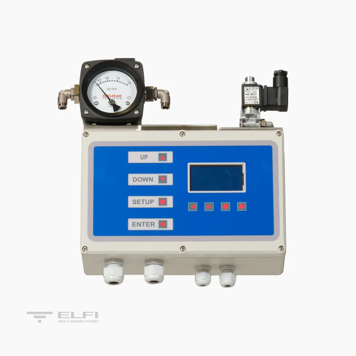
| Solenoid valve – Volt /Watt | 24 AC /6 | 24 AC /6 | 24 AC /6 | 24 AC /6 | 24 AC /6 | 24 AC /6 | 24 AC /6 | 24 AC /6 |
| Pneumatic supply - Bar | 2 - 8 | 2 - 8 | 2 - 8 | 2 - 8 | 2 - 8 | 2 - 8 | 2 - 8 | 2 - 8 |
| Construction certificates | CE | CE | CE | CE | CE | CE | CE | CE |
| Maximum size of inlet particles – mm |
10 | 10 | 10 | 10 | 10 | 10 | 10 | 10 |
| Max total suspendedsolids at inlet 125 micron – mg/l | 30 | 30 | 30 | 30 | 30 | 30 | 30 | 30 |
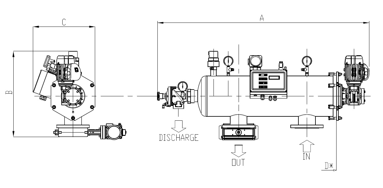
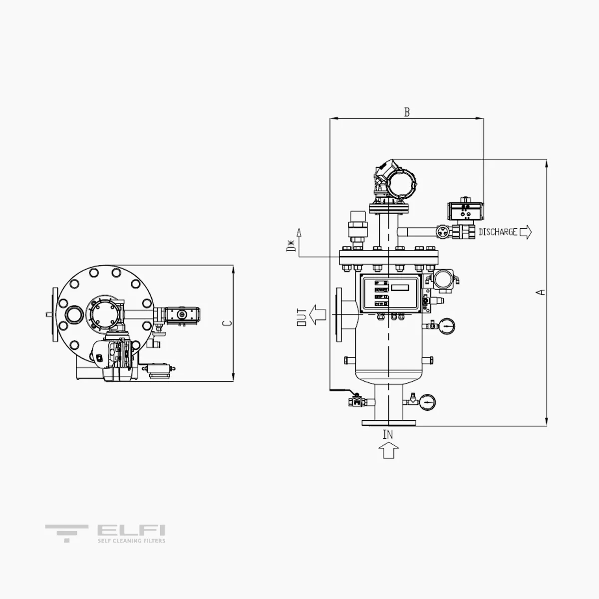
| A (mm) | 757 | 903 | 1071 | 1309 | 1755 | 2027 | 2581 | 3181 |
| B (mm) | 485 | 505 | 645 | 745 | 800 | 905 | 968 | 1114 |
| C (mm) | 327 | 423 | 423 | 516 | 714 | 852 | 852 | 852 |
| D (mm) Cartridge extraction | 450 | 600 | 640 | 885 | 1130 | 1160 | 1160 | 1690 |
| WEIGHT when empty Kg | 34 | 51 | 62 | 72 | 85 | 127 | 223 | 305 |
| WEIGHT in operation Kg | 42 | 51 | 81 | 116 | 143 | 214 | 356 | 618 |
TECHNICAL DATA AND DIMENSIONS | SP O
| MODEL | SP O 10 | SP O 15 | SP O 30 | SP O 45 | SP O 60 | SP O 75 | SP O 90 | SP O 130 |
|---|---|---|---|---|---|---|---|---|
| Filtering area (cm²) | 1000 | 1500 | 3000 | 4500 | 6000 | 7500 | 9000 | 13000 |
| Connections- In/Out | 2" | 3" | DN100 | DN150 | DN200 | DN250 | DN300 | DN350 |
| Discharge connection | 1"1/2F | 1"1/2F | 2"F | 2"F | 2"F | 2"F | 2"F | 2"F |
| Washing flow rate - m³/h | 5 | 10 | 15 | 20 | 24 | 24 | 35 | 45 |
| Wash duration - Sec. | 15 | 15 | 15 | 15 | 15 | 15 | 15 | 15 |
| Min-max pressure - Bar | 0,5-10 | 0,5-10 | 0,5-10 | 0,5-10 | 0,5-10 | 0,5-10 | 0,5-10 | 0,5-10 |
| Max Temperature - °C | 50 | 50 | 50 | 50 | 50 | 50 | 50 | 50 |
| Power supply - Volt | 400 50/60 Hz | 400 50/60 Hz | 400 50/60 Hz | 400 50/60 Hz | 400 50/60 Hz | 400 50/60 Hz | 400 50/60 Hz | 400 50/60 Hz |
| Power required - Watt | 90 | 180 | 180 | 180 | 370 | 370 | 370 | 550 |
| Solenoid valve - Volt / Watt | 24 AC / 6 | 24 AC / 6 | 24 AC / 6 | 24 AC / 6 | 24 AC / 6 | 24 AC / 6 | 24 AC / 6 | 24 AC / 6 |
| Pneumatic supply - Bar | 2 - 8 | 2 - 8 | 2 - 8 | 2 - 8 | 2 - 8 | 2 - 8 | 2 - 8 | 2 - 8 |
| Construction certificates | CE | CE | CE | CE | CE | CE | CE | CE |
| Maximum size of inlet particles – mm | 30 | 30 | 30 | 30 | 30 | 30 | 30 | 30 |
| Max total suspended solids at inlet – 125 micron mg/l | 30 | 30 | 30 | 30 | 30 | 30 | 30 | 30 |
| A (mm) | 940 | 1185 | 1430 | 1675 | 1920 | 2055 | 2200 | 2700 |
| B (mm) | 470 | 585 | 590 | 595 | 625 | 685 | 885 | 1195 |
| C (mm) | 330 | 420 | 420 | 485 | 625 | 795 | 1040 | 1195 |
| D (mm) * Cartridge extractiona | 250 | 400 | 585 | 640 | 810 | 850 | 1040 | 1230 |
| WEIGHT when empty Kg | 25 | 29 | 46 | 52 | 82 | 125 | 200 | 288 |
| WEIGHT in operation Kg | 33 | 42 | 72 | 91 | 116 | 222 | 370 | 628 |


