Description
HOW IT WORKS
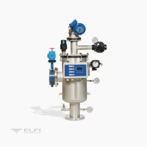
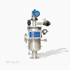
Water enters the filter through the (1) inlet and goes through the filtering cylinder from the inside to the outside. This will retain all suspended solids that are the same size or bigger than the filtration degree installed. Filtered water leaves through the outlet pipe (2).
REGENERATION
When the differential pressure gauge reaches the pre-set pressure difference between filter inflow and outflow, a signal is triggered and the cleaning starts. This operation is divided into three separate phases:
- The first phase is the closure of the inlet valve (1) with consequent closure of the outflow check valve (2)
- In the second phase the vessel is emptied through the discharge valve (3)
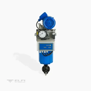
- The third phase is the actual cleaning: the washing inlet valve opens (4) and through the manifold (5) feeds the nozzles (6), at the same time the electric motor (7) powers the rotations of the cleaning systems.
The washing pressure range from a minimum of 2 Bar to maximum of 10 Bar.
Average length of the cleaning cycle is 120 sec.
CONTROL
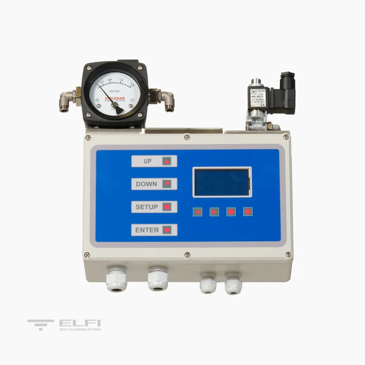
A switchboard controls the washing phases. The signal that starts the cleaning cycle is given by a differential pressure switch or by time. The switchboard gives an “alarm” signal in case of problems in the washing system. These signals can be sent to a pre-existing control center.
The washing phase can also be controlled manually. The solenoids controlling the valves are pneumatic.
SPRAY NOZZLE SELF CLEANING FILTER US
Technical Specifications
| MODEL | US 15 | US 30 | US 45 | US 60 | US 90 |
|---|---|---|---|---|---|
| Filtering area (cm²) | 1500 | 3000 | 4500 | 6000 | 9000 |
| Connections- In/Out | DN80 | DN80 | DN100 | DN100 | DN150 |
| Connection Discharge | 1″1/2 F | 2″ F | 2″ F | 2″ F | DN80 |
| Connection Washing inlet | 1″ F | 1″1/2 F | 1″1/2 F | 1″1/2 F | 1″1/2 F |
| Washing flow rate at 3 Bar – m³/h | 2 | 3 | 3 | 3 | 5 |
| Wash duration – Sec | 80 | 80 | 80 | 80 | 80 |
| Min-max pressure – Bar | 0,5-10 | 0,5-10 | 0,5-10 | 0,5-10 | 0,5-10 |
| Max Temperature – °C | 40 | 40 | 40 | 40 | 40 |
| Power supply – Volt | 400 | 400 | 400 | 400 | 400 |
| Power supply – Hz | 50/60 | 50/60 | 50/60 | 50/60 | 50/60 |
| Power required – Watt | 90 | 180 | 180 | 180 | 370 |
| Electric valve – Volt/Watt | 24 AC / 6 | 24 AC / 6 | 24 AC / 6 | 24 AC / 6 | 24 AC / 6 |
| Pneumatic supply – Bar | 2 – 8 | 2 – 8 | 2 – 8 | 2 – 8 | 2 – 8 |
| Construction certificates | CE | CE | CE | CE | CE |
| *Maximum size of inlet particles – mm | 5 | 5 | 5 | 5 | 5 |
| Max total suspended solids at inlet – 120 micron – mg/l | 20 | 20 | 20 | 20 | 20 |
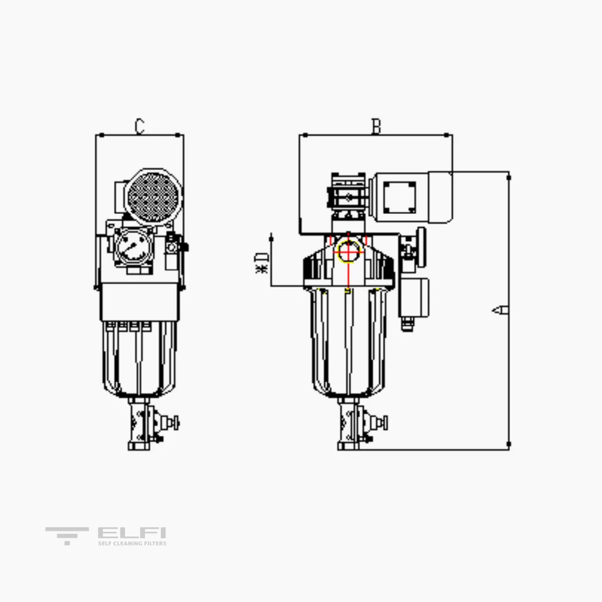
| A (mm) | 1025 | 1190 | 1440 | 1440 | 1690 |
| B (mm) | 455 | 580 | 580 | 620 | 715 |
| C (mm) | 380 | 480 | 570 | 570 | 705 |
| D (mm) Cartridge extraction | 600 | 640 | 885 | 885 | 1160 |
| WEIGHT when empty Kg | 34 | 44 | 64 | 64 | 116 |
| WEIGHT in operation Kg | 55 | 88 | 83 | 106 | 133 |
Parts Description
| PART | DESCRIPTION |
|---|---|
| Body | AISI316 – SAF2205 – SAF2507 |
| Cover | AISI316 – SAF2205 – SAF2507 |
| Connection threading | BSP |
| Flange connection | EN 1092-1 PN10 |
| Mesh support strainer | PVC – AISI316 |
| Filtering mesh | Polyester – AISI316: 500, 300, 200, 125, 80, 50, 25 µm |
| Spray nozzle | PVDF |
| Nozzle pipe | PVC – AISI316 |
| Internal seals | EPDM |
| Reduction unit | Aluminium and carbon steel |
| Electric motor | Hot-painted aluminium |
| Solenoid valve | Three-way aluminium |
| Switchboard | ABS IP65 with front display |
| Differential pressure switch | Aluminium with parts in contact with liquid made of AISI 316 |
| Butterfly valve | AISI316 with pneumatic actuator |
| Ball valve | AISI316 with pneumatic actuator |
| Vent | PA automatic |
| Accessories (Plugs and adapters) | PVC- AISI316 |


