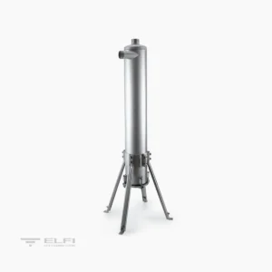
Description
HOW IT WORKS
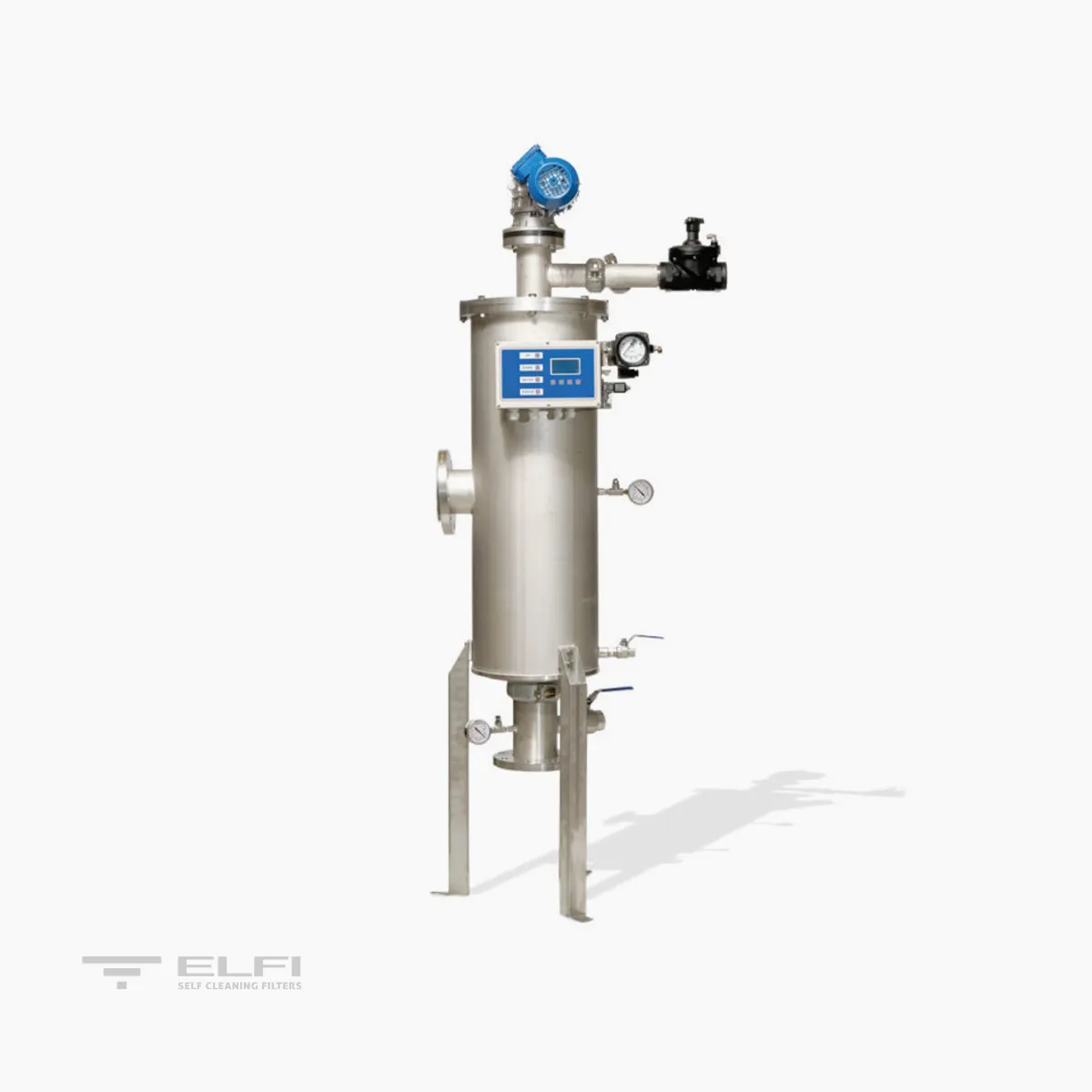
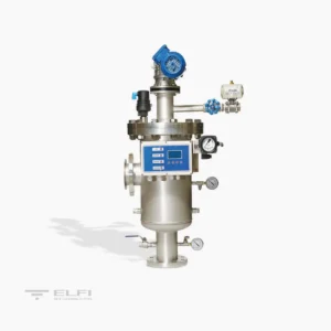
Water enters the filter through the IN inlet and goes through the filtering cylinder (4) from the inside to the outside. This will retain all non-deformable suspended solids that are the same size or bigger than the filtration degree installed. Filtered water leaves through the outlet pipe (OUT).
REGENERATION
Constant deposit of suspended solid particles inside the filtering cylinder (1) obstructs the passage of water, causing a pressure differential (∆P). At a preset ∆P value (ranging from 0.2 ÷ 0.4 Bar) an automatic cleaning cycle of the filtering (1) cylinder starts. This activity begins with a signal that opens the discharge valve (2) allowing communication of the suction nozzles (3) with the outside environment. At the same time, the electric motor’s (4) rotary motion allows the nozzles to inspect the entire filtering surface. Dirt is removed through the discharge valve (2). The cleaning cycle lasts 15 sec.
CONTROL
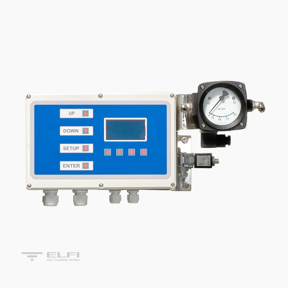
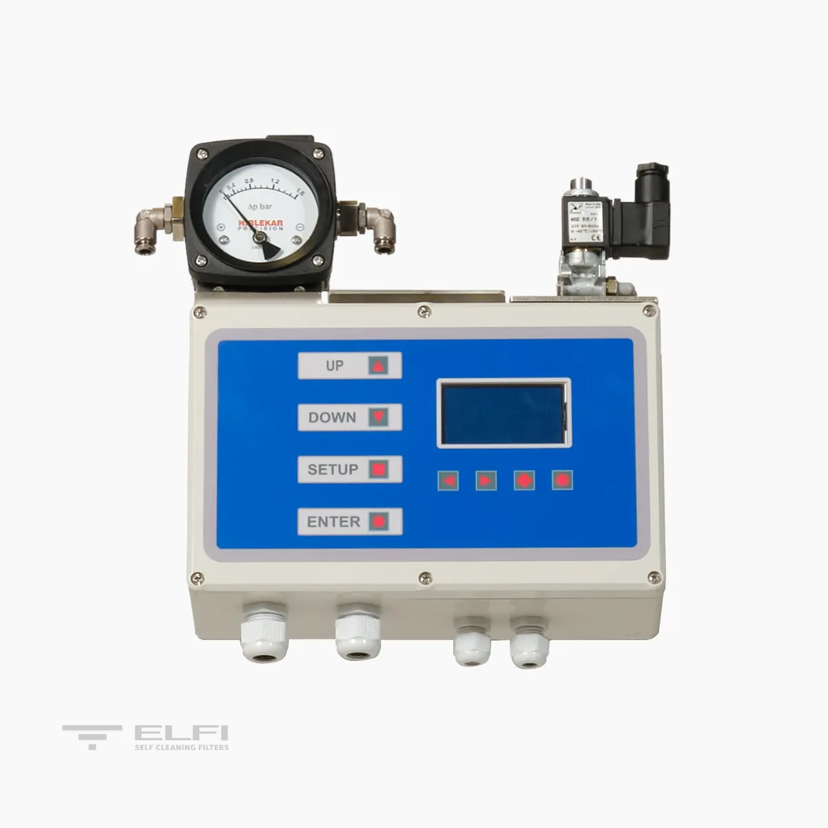
A switchboard controls the washing phases. The signal that starts the cleaning cycle is given by a differential pressure switch or by time. The switchboard gives an “alarm” signal in case of problems in the washing system. These signals can be sent to a pre-existing control centre. The washing phase can also be controlled manually. The solenoid controlling the valve is pneumatic.
3D FILTERING TECHNOLOGY
The filtering element of the filtering fabric is made of AISI316 sintered fibre. This ensures high permeability with excellent filtering efficiency owed to the fabric’s thickness (hence called 3D) and the diameter of the fibres. At equal surface and pressure differential, this type of construction allows retention of a much greater amount of TSS (Total Suspended Solids) compared with traditional single thread fabrics. Additionally, exposed to Delta P, the fibres are far more stable compared with single thread fabrics. The filtering fabrics used are tested in our laboratories to assess the performance of the main filtering process.
Based on performance assessments, the most suitable fabrics for the requested use are selected.
DIMENSIONI E DATI TECNICI | SCR LM

| MODELLO | SCR L M 10 | SCR L M 30 | SCR L M 65 | SCR L M 90 | SCR L M 130 |
|---|---|---|---|---|---|
| Area filtrante (cm²) | 1000 | 3000 | 6500 | 9000 | 13000 |
| Attacchi In/Out | 2" BSP | DN80 | DN80-DN100 | DN100 – DN150 | DN150-DN200 |
| Attacchi Scarico | 1" | 2" F | 2" F | 2" F | 2" F |
| Attacchi svuotamento | 1/2" F | 1/2" F | 1/2" F | 1" F | 1" F |
| Extra portata richiesta in lavaggio a 1 Bar con tessuto da 5 micron – m³/h | 4 | 4 | 8 | 9 | 14 |
| Durata del lavaggio – Sec. | 20 | 20 | 20 | 20 | 20 |
| Pressione min-max – Bar | 1-10 | 1-10 | 1-10 | 1-10 | 1-10 |
| Temperatura max – °C | 50 | 50 | 50 | 50 | 50 |
| Alimentazione elettrica – Volt | 400 50/60 Hz | 400 50/60 Hz | 400 50/60 Hz | 400 50/60 Hz | 400 50/60 Hz |
| Potenza richiesta – Watt | 90 | 180 | 180 | 370 | 550 |
| Elettrovalvola – Volt / Watt | 24 AC / 6 | 24 AC / 6 | 24 AC / 6 | 24 AC / 6 | 24 AC / 6 |
| Alimentazione pneumatica – Bar | - | - | 2 – 8 | 2 – 8 | 2 – 8 |
| Norme di calcolo vessel | EN13445 | EN13445 | EN13445 | EN13445 | EN13445 |
| Certificati di costruzione | CE | CE | CE | CE | CE |
| Massima dimensione di particelle in ingresso – mm | 0.2 | 0.2 | 0.2 | 0.2 | 0.2 |
| Massimo totale solidi sospesi in ingresso 20 micron – mg/l | 20 | 20 | 20 | 20 | 20 |
| Massimo totale solidi sospesi in ingresso 10 micron – mg/l | 10 | 10 | 10 | 10 | 10 |
| Massimo totale solidi sospesi in ingresso 5 micron – mg/l | 5 | 5 | 5 | 5 | 5 |
| Piedi | inclusi | inclusi | inclusi | inclusi | inclusi |
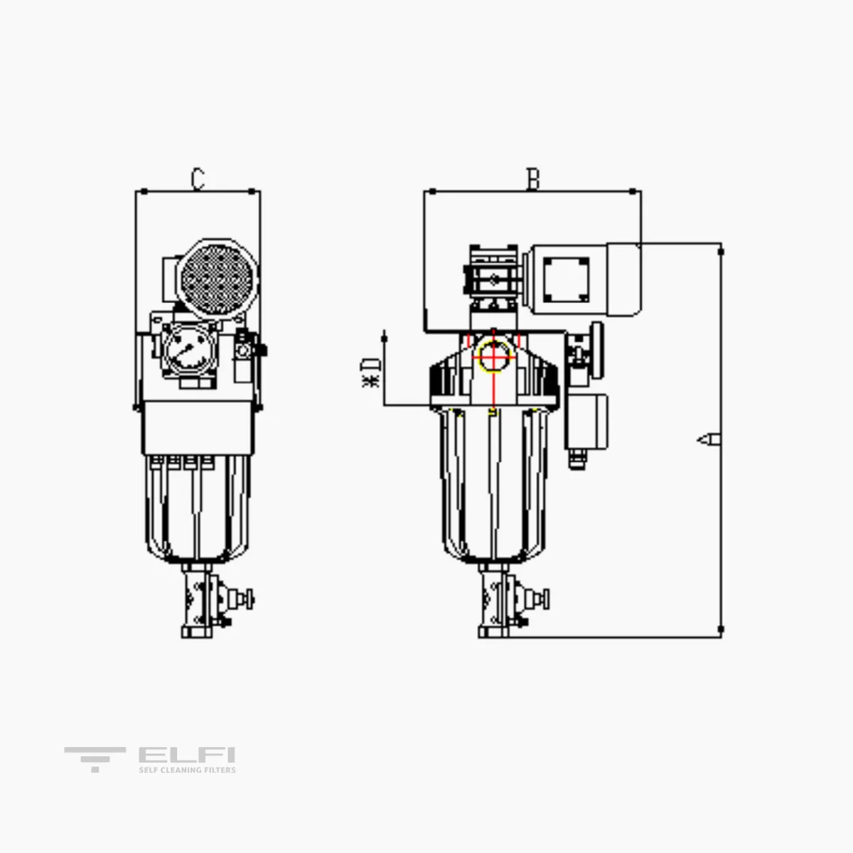
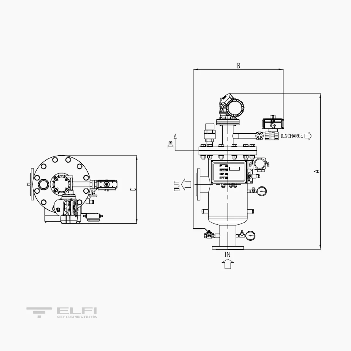
| A (mm) | 965 | 1420 | 1860 | 1930 | 2330 |
| B (mm) | 440 | 710 | 710 | 800 | 910 |
| C (mm) | 390 | 530 | 530 | 645 | 755 |
| D (mm) Estrazione cartuccia | 450 | 590 | 1030 | 1150 | 1650 |
| PESO a vuoto Kg | 32 | 64 | 81 | 190 | 238 |
| PESO in lavoro Kg | 103 | 157 | 325 | 523 | 523 |
DIMENSIONI E DATI TECNICI | SCR OM

| MODELLO | SCR L OM 65 | SCR L M 90 | SCR L M 130 |
|---|---|---|---|
| Area filtrante (cm²) | 6500 | 9000 | 13000 |
| Attacchi In/Out | DN80-DN100 | DN100 – DN150 | DN150-DN200 |
| Attacchi Scarico | 2" F | 2" F | 2" F |
| Attacchi svuotamento | 1/2" F | 1" F | 1" F |
| Extra portata richiesta in lavaggio a 1 Bar con tessuto da 5 micron – m³/h | 8 | 9 | 14 |
| Durata del lavaggio – Sec. | 20 | 20 | 20 |
| Pressione min-max – Bar | 1-10 | 1-10 | 1-10 |
| Temperatura max – °C | 50 | 50 | 50 |
| Alimentazione elettrica – Volt | 400 50/60 Hz | 400 50/60 Hz | 400 50/60 Hz |
| Potenza richiesta – Watt | 180 | 370 | 550 |
| Elettrovalvola – Volt / Watt | 24 AC / 6 | 24 AC / 6 | 24 AC / 6 |
| Alimentazione pneumatica - Bar | 2 – 8 | 2 – 8 | 2 – 8 |
| Norme di calcolo vessel | EN13445 | EN13445 | EN13445 |
| Certificati di costruzione | CE | CE | CE |
| Massima dimensione di particelle in ingresso – mm | 0.2 | 0.2 | 0.2 |
| Massimo totale solidi sospesi in ingresso 20 micron – mg/l | 20 | 20 | 20 |
| Massimo totale solidi sospesi in ingresso 10 micron – mg/l | 10 | 10 | 10 |
| Massimo totale solidi sospesi in ingresso 5 micron – mg/l | 5 | 5 | 5 |
| Piedi | inclusi | inclusi | inclusi |
| A (mm) | 1860 | 1930 | 2430 |
| B (mm) | 710 | 840 | 910 |
| C (mm) | 530 | 645 | 755 |
| D (mm) Estrazione cartuccia | 1030 | 1150 | 1650 |
| PESO a vuoto Kg | 81 | 190 | 238 |
| PESO in lavoro Kg | 157 | 325 | 523 |
FLOW RATE
| MODEL | 20 µm 3D AISI316 | 10 µm 3D AISI316 | 5 µm 3D AISI316 |
|---|---|---|---|
| SCR L M 2-10 | 20 | 15 | 10 |
| SCR L M 80-30 | 60 | 45 | 30 |
| SCR L M 80/100-65 | 130 | 97 | 65 |
| SCR L M 100/150-90 | 180 | 135 | 90 |
| SCR L M 150/200-130 | 260 | 195 | 130 |


